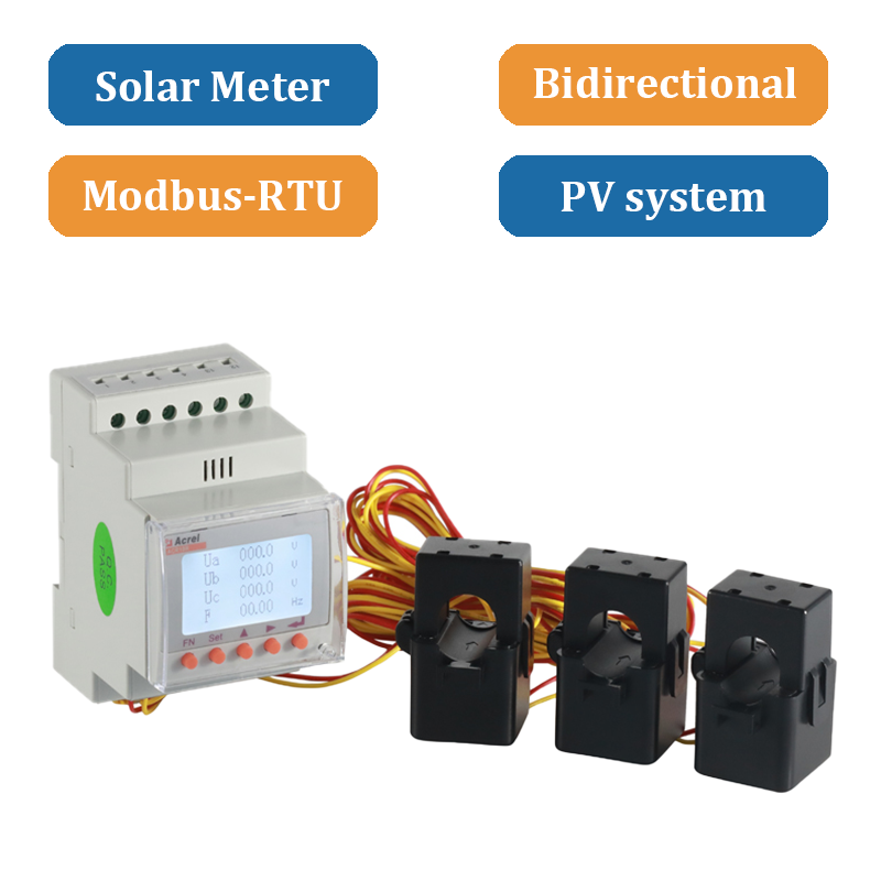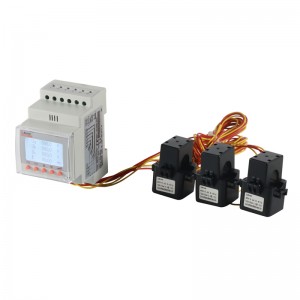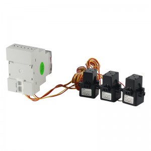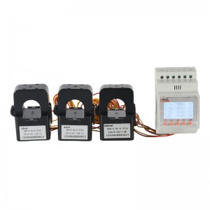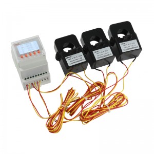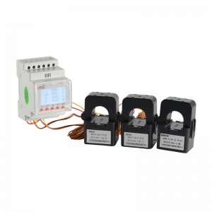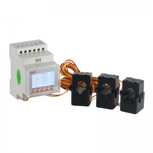
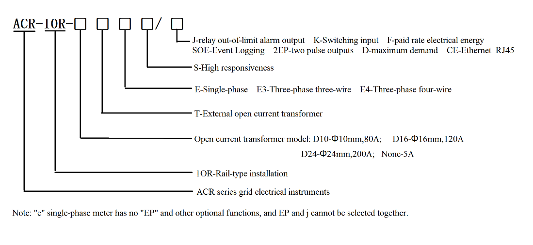
ACR10R-DxxTE4 Din-rail type 3 Phase Solar Energy Meter
General
The rail-type multifunction electrical instrument with external Rogowski coil and split-core current transformer is applicable for the energy-saving reconstruction project in high energy consumption industries including the smelting, iron and steel, welding and semi-conductor industry. It boasts of no need of bus removal, easy connection and safe construction, saving reconstruction cost and raising efficiency for the user. It integrates the measurements of all electric parameters (including single-phase current, voltage, active power, reactive power, apparent power, frequency and power factor)and comprehensive energy monitoring and examination management. Meanwhile, it also has various peripheral interfaces for the user to choose: the RS485 communication interface with MODBUS-RTU protocol can meet the need of online communication management; the interfaces with switch input and relay output can realize the remote signalling and remote control of the circuit breaker switch. It is very suitable for real-time power monitoring system with an LCD display and the panel buttons to realize the setting and control of parameters.
It is also suitable for applications such as the power monitoring of grid-connected cabinet for distributed photovoltaic power cabinet and energy demand management. This energy meter is designed for inverters in solar system. There is bidireactional function, which is able to measure reverse power and transfer signal to inverters.
Specification
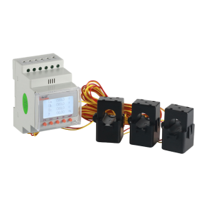
Function
Frequency Range:45~65Hz
Auxiliary power supply AC85~265V
Rated current 80A, 120A, 200A, 300A
Consumption Voltage:Power consumption:<0.2VA; Current:Power consumption:< 0.2VA; Auxiliary power supply:power consumption≤10VA
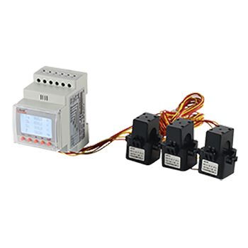
Size
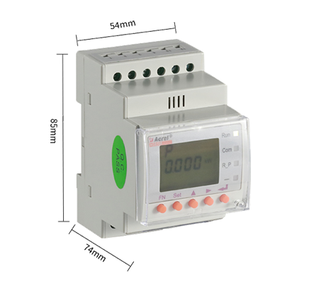
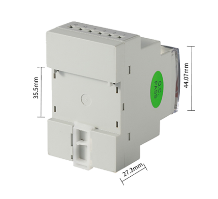
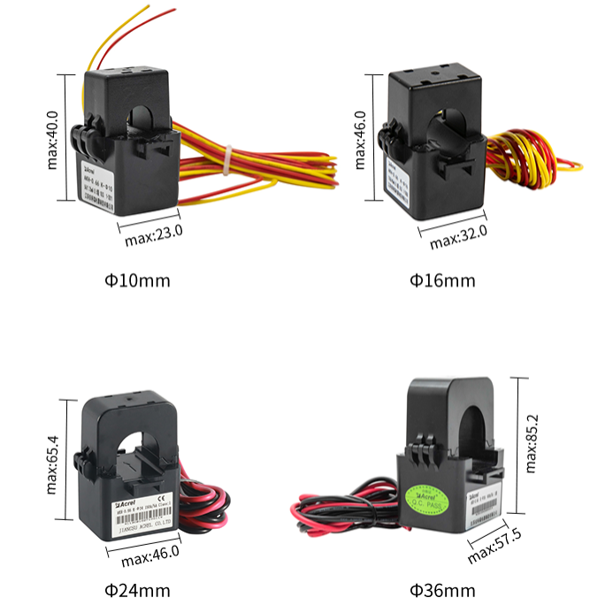
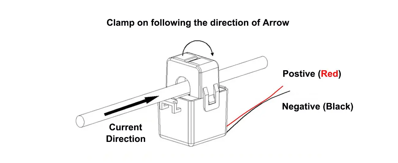
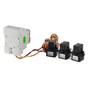
Structure
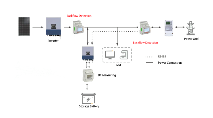
Application
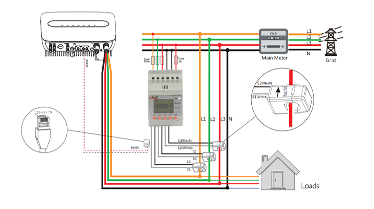
1.Technical parameter
1.1 Electrical performance
|
Technical parameters |
Indicators |
||
|
Input |
Grid |
Three-phase three-wire/three-phase four-wire |
|
|
Frequency |
45~65Hz |
||
|
Voltage |
Rated voltage:AC 57.7V/100V(100V)、220V/380V(400V) |
||
|
Overload: 1.2 times the rated voltage(continuous); 2 times the rated voltage lasting for 1 second |
|||
|
Power consumption: less then 0.2VA |
|||
|
Current |
Rating: with external transformer 80A/26.7mA,120A/40mA,200A/66.66mA With built-in mutual sensor:5A |
||
|
Overload: 1.2 times the rated current(continuous);10 times the rated current lasting for 1 second |
|||
|
Power consumption: less then 0.2VA |
|||
|
Output |
Electricity |
Output mode:Open collector optocoupler pulse, 2-way output |
|
|
Three-phase |
Pulse constant:100imp/kWh |
||
|
Communication |
RS485 interface, Modbus-RTU、Ethernet |
||
|
Display |
LCD |
||
|
Switch |
Input |
4 dry contact inputs |
|
|
Output |
Output mode: 2-way relay normally open contact output |
||
|
Contact capacity:AC 250V/3A、DC 30V/3A |
|||
|
Measurement precision |
0.5 level, Reactive energy: 2 level、Other: 1 level |
||
|
Power supply |
AC85~265V, power consumption≤10VA |
||
|
Safety |
Power frequency withstand voltage |
AC2kV between power//switching output//current input and voltage input//communication//pulse output//switching input 1min. Power supply//switching output//current input and voltage input between two two AC2kV 1min. AC1kV between communication//pulse output//switching input two by two 1min. |
|
|
Insulating resistor |
Input and output to chassis >100MΩ |
||
1.2 Work environment
|
Environment |
Temperature |
Working:-10℃~+55℃ Storage:-25℃~70℃ |
|
Humidity |
Relative humidity 5%~95% (non-condensing) |
|
|
Altitude |
≤2500m |
2. Functional Characteristic
2.1 Basic & Optional Function
|
Function |
ACR10R-(DxxT)E3/4 |
|
|
Display method |
LCD (field LCD) |
■ |
|
Measurement parameters |
Current/voltage/frequency/power factor |
■ |
|
Active/reactive power/apparent power |
■ |
|
|
Four-quadrant power measurement |
■ |
|
|
Maximum demand |
■ |
|
|
Complex rate power metering |
■ |
|
|
Data logging |
Event logging |
□ |
|
Alarm |
□ |
|
|
|
Built-in clock |
■ |
|
Communication |
RS485 interface |
■ |
|
Ethernet interface |
□ |
|
|
RJ45 interface |
□ |
|
|
Optional function (choose one) |
Relay output (2DO) |
A1+(B1 or C1) (4DI+2DO or 4DI+EP)* |
|
Communication |
Switching input (4DI) |
■ |
|
Optional function (choose one) |
Pulse output (2 channels) |
A1+(B1 or C1) (4DI+2DO or 4DI+EP)* |
“■” means standard, “□” means optional.
Note:
1. The standard configuration for above instruments is 1 channel RS485 communication.
2. A1/B1/C1 etc. in the optional function corresponds to the terminal wiring method of 5.4.
3. Pulse output and relay output are not optional at the same time.
4. When the optional event logging function is equipped, the DI or DO function must be configured.

